Flowing Artesian Water Well Control Methods
“Flowing artesian” wells mean:
- Natural water level rises above the ground surface or top of the casing
- Water is observed to flow naturally, either intermittently or continually
A flowing artesian well is “controlled” when:
- The whole of the flow is conveyed through the production casing
- The flow does not pose a risk to property, environment or public safety, and the flow can be indefinitely stopped without leakage
Artesian conditions arise when there is a movement of groundwater from a recharge area under a confining formation to a point of discharge at a lower elevation. An example of this is a natural spring, or in the example of the drilling industry, a flowing water well.
Groundwater recharge areas may consist of higher elevation lakes or swamps/muskegs, or exposed sand and gravel formations, fractured bedrock, or other permeable formations. The confining formations may consist of: clay formations, glacial till deposits, impervious bedrock formations. Groundwater flow conditions can vary to a great degree within local areas depending upon local geological conditions.
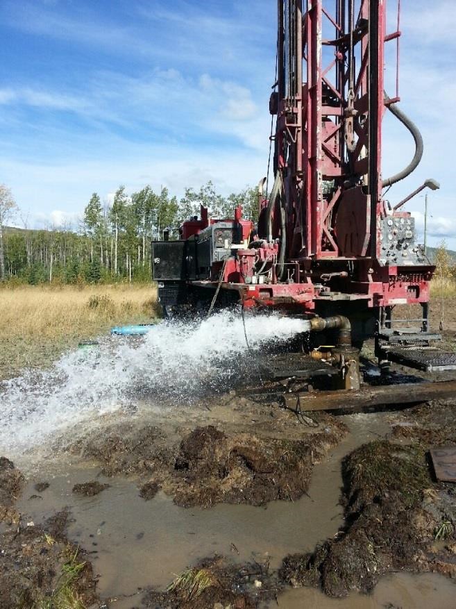
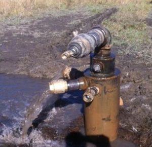 Flowing artesian wells are generally controlled by the use of a sealed surface casing and the use of control valves on the production casing. As seen in the Figure 1, the use of multiple pressure relief fittings may be required to gain control of a flowing well. With these fittings, cement grout can be pumped between the production and surface casing against the artesian flow that may be moving upward toward the surface.
Some knowledge of the artesian pressure and artesian formation depth(s) is required, so that when pumping the grout, one does not overpressure the confining formation and cause a condition known as a “Frac- Out”. A Frac-Out (also known as hydraulic fracture) may occur close to the well or at some distance away, and may result in artesian flows coming to surface in unexpected locations.
A commonly used “rule of thumb” calculation for confining ground weight could be: 1 ft. of overburden material will hold back approximately 1 psi of formation pressure.
Example of pressure in an artesian condition: Artesian flow encountered at 100 ft. below ground elevation, artesian pressure measured at 10 psi at surface. The weight of the water column is 100ft / 2.41 ft/psi = 43.29 psi. The weight of the ground is about 100psi. Ground weight minus column weight is 56.71 psi. Ground pumping pressures nearing 56 psi have the potential of causing a Frac-Out condition.
Grout can be pumped from 10+ psi to 70 psi (safety factor) to fill voids between the production casing and the ground formations and to seal the annulus between the production casing and surface casing. The rate at which an artesian formation will accept grout will vary due to the available porosity of the geological unit. For example, coarse, clean gravels will accept pumped fluids at a faster rate than fine grained sand because of the pore capacity.
Installing Surface Casing
Different methods of drilling require different strategies for installing the surface casing.
- Mud Rotary Method
- Air Rotary/Casing Hammer Method
- Cable Tool
Mud Rotary
In this method, the hole is drilled open, surface casing is installed, and then grout is pumped in to displace fluids in the annulus between the casing and the geological formation. To calculate the volume of grout required to seal the surface casing and the formation, the volume of the open hole is first calculated, and then the enclosed volume of the surface casing is subtracted from the total volume of the hole. The open hole must be drilled to a suitable depth in a competent formation (such as clay or bedrock) in order to provide an adequate surface seal. Creating a suitable seal with the cement grout minimizes the potential for artesian groundwater pressures to cause water to flow outside of the casing. When the desired depth of casing has been installed in the open hole with a flow fitting welded to the side, the casing installation is typically completed in the following manner:
- The surface casing should be suspended six to twelve inches from the bottom of the hole, and a flange welded to the top of the surface casing.
- The predetermined volume of cement grout can be installed in the inner annulus of the surface casing.
- A cementing plug is installed from surface. A flange plate with a valved outlet and pressure gauge is bolted on to the welded flange.
- Clean water can be pumped through the valve on the flange, forcing the grout to the bottom of the surface casing. The grout will be forced up the annulus between the surface casing and the formation surface.
- When the cementing plug comes to the bottom of the surface casing, a pressure rise will occur, indicating that all grout material has been displaced from the inside of the surface casing.
- At this time close the valve and disconnect the grout pumping equipment. The grout should be allowed time to set up before further drilling is undertaken, usually 12 – 24 hours depending upon the density of the cement grouting material and additives / accelerators.
- After the grout has set, the flange can be removed and drilling can be continued on the production well.
- After drilling to the desired depth has been completed and production casing has been installed, a slip-on flange complete with gasket can be installed over the production casing, bolted to the surface casing, and then welded to the production casing, thereby insuring a water tight seal. The valve on the side of the surface casing can also be closed.
- If desired, cement grout may be pumped between the surface casing and the production casing through the valved flow fitting for extra sealing of the production well.
- A slip-on flange can be welded to the top of the production casing and then a bolt-on flange complete with gasket can be installed to control the flow out of the production casing.
- Proper planning and execution of the drilling program should ensure a successful flowing artesian well installation.
Air Rotary Casing Hammer
In this method of drilling, surface casing can be placed in a shorter length of time than using the Mud Rotary Method. Similar to driving a steel pipe piling, a seal is formed between the geological formation and the surface of the steel pipe being driven.
Some knowledge of artesian groundwater flows, pressures, and geological conditions within the local area is a valuable asset in determining the amount of surface casing that will be required to provide a suitable seal.
Installation of surface casing for a flowing artesian well is typically undertaken in the following manner:
- Select the size of surface casing to be installed. The inside diameter of the surface casing should be a minimum of 2 inches larger than the outside diameter of the pipe used in drilling the production well.
- The selected surface casing is hoisted into the drilling rig derrick complete with drill rod, and an appropriately sized drilling bit, that will be used to clean the inside of the surface casing as it is advanced.
- No drive shoe will be installed on the surface casing, since a drive shoe is slightly larger than the pipe and could potentially reduce the effectiveness of the surface seal.
- Surface casing will be driven downward until a competent sealing formation is encountered, such as clay or dense silty clay materials. As casing is driven downward, soil can be removed from the inside of the casing with the drill bit and air circulation. It is recommended that the drill bit not be advanced ahead of the end of the casing.
- With careful monitoring and logging of the recovered formation samples during drilling, it can be determined how far the casing has been advanced in competent material. Additionally, the skin friction between the outside of the driven casing and the natural ground will increase once suitably competent material has been reached, and the number of hammer blows per foot of casing advance will tend to increase.
- As a general rule, it is recommended that a minimum of 40 feet (12m) or more of surface casing be installed in all flowing artesian wells.
- When the surface casing has been advanced to a suitable depth, the drill rods and drill bit can be removed from the hole.
- A slip-on flange ring can be welded to the surface casing complete with an overflow nipple that has been welded to the outside of the casing. A valve can also be installed on the overflow fitting for future use.
- Drilling of the production casing within and beyond the surface casing can now be undertaken to complete the water well as required.
- Flows may occur between the production casing and surface casing during the completion of the production well, but such flows will be placed under full control following completion of production well drilling.
- Once the production casing has reached the desired depth, the drill rods and bit can be removed from the hole.
- At this time, a decision can be made whether the well should_be screened or not dependant on its intended use, formation graine size distribution, and the volume of water flowing from the well.
- Now that the well has been completed as desired, the flow control fittings can be attached to the casing and/or well cap at the surface.
- A Slip-On bolt flange complete with gasket can be slid over the production casing and bolted to the welded flange on the surface casing. This can then be welded to the outside of the production casing to control any flow between the production and surface casings. The valve on the flow control nipple can now be closed to control any flow occurring between the two casings.
- Flow control of the production casing can now be undertaken.
- Water levels will have to be lowered within the production well casing in order to weld on a Slip-On bolted flange and a flow control nipple on the side of the casing.
- Water levels can be controlled within the production casing using a portable engine driven pump, or if desired, a submersible electrical pump complete with a valve. Pumping will lower the water level below the elevation of the top of the casing such that all appropriate fittings can be welded to the production casing.
- Once all fittings are attached, the pump can be removed from the production well.
- The bolt-on flange and gasket can now be bolted in place and the attached flow valve can be closed.
- The valve on the flow nipple can also be closed
- The well should now be in control, and flows through the valves should also be controllable.
- If desired, grout can be pumped through the valve on the surface casing to obtain a grout seal between the two casings.
In all drilling programs planning is essential for the successful completion of the project. Knowledge of the geology of the area, required materials for the project and equipment to do the job are required for a successful completion of a drilling program.
Cable Tool
When a cable tool drill rig is used to drill a flowing artesian well, surface casing can be installed using either the mud rotary method or the air rotary method whichever is desired. One method may be more practical than the other, dependent upon the drilling equipment utilized to complete the well. As in all drilling programs, preplanning and execution of good drilling practices aid in the successful completion of the project.
British Columbia has over 357 thousand square miles of land area within the provincial boundaries. Within this land mass there are varied geological formations. There are some recorded flowing artesian formations and many more to be discovered as drilling continues. One of the least explored areas within the province is on the east side of the Rocky Mountains in the north-east section of the province (Peace River District). Artesian conditions will likely be encountered while drilling for the Oil & Gas industry, since much of the rural population in the area relies on either surface water dugouts, or cisterns with hauled water for their water supply.
Drilling programs conducted by the Oil & Gas sector vary greatly. These include: seismic exploration, water injection supply wells, and soils investigations for pipeline river crossings, drive pile installation programs, and slope stability assessments. While conducting these types of drilling programs, flowing artesian conditions have been encountered.
Many of these holes have been drilled without the use of surface casing, making the control of water flows much more difficult. Inflatable packers and bentonite have been used to control and stop flows with some success, but the locations and geological conditions at most of those sites have not been recorded, and the long term success or failure of such seals is uncertain. There are potential detrimental effects on the environment, and on the groundwater resource when drilling in artesian conditions without the appropriate equipment and materials.
The ultimate impact on the environment and the groundwater resource will likely continue to be debated for some time to come.
Pressurized Formations
Sometimes in drilling programs there are formations that are encountered that are not expected. They may be flowing artesian formations or formations containing natural gasses such as carbon dioxide, methane, or hydrogen sulphide (H2S).
Encountering these gasses creates some very unique problems. Carbon dioxide gasses, in sufficient quantities, can create a low oxygen atmosphere and create a safety hazard. Methane gasses, in quantities, can create an explosive atmosphere as well a fire hazard. H2S in very low percentages can cause suffocation and possibly death. The possibility of encountering these formations increases when working on the east side of the Rockies (e.g. the Peace River area) in northern B.C. where shale gas resources are known to exist.
This article has been prepared in good faith to assist water well professionals working in flowing artesian environments. Every well is unique and requires site-specific planning. Any use, interpretation, or reliance on the information presented herein is at the sole risk of that party, and neither the author nor the BC Ground Water Association accept any liability for injury or damage resulting thereof.
The editor invites members to share their expertise within this newsletter and help grow a better understanding within our industry.